Carson SA-441-83FX User Manual
Browse online or download User Manual for Car amplifier Carson SA-441-83FX. Carson SA-441-83FX User Manual
- Page / 10
- Table of contents
- BOOKMARKS
Rated. / 5. Based on customer reviews
TB0335B Page 1 of 10 10/18/03
Carson
MANUFACTURING COMPANY, INC.
CARSON MANUFACTURING CO., INC.
5451 NORTH RURAL STREET
INDIANAPOLIS, IN 46220
(888) 577 6877 www.carsonsirens.com
TECHNICAL BULLETIN
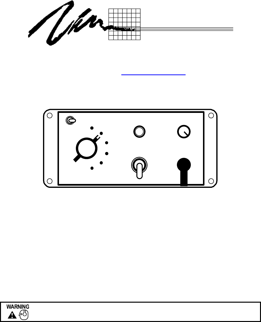
SA 441SA 441
RADIORADIO
HRN/TT
HRN/TT
MANMAN
WAILWAIL
YELPYELP
PHASR/WPHASR/W--YY
SIRENSIREN
PA
VOL
POWERPOWER
OFF/ON
ON
INSTALLATION AND
OPERATING MANUAL
SA-441-83F (FLUSH MOUNT CONTROL HEAD)
SA-441-83FX (FLUSH MOUNT WITH EXTENDED MIC)
Sound Hazard - Sound level from siren speaker (>120dBA @ 10 feet) may cause hearing damage.
Do not operate siren without adequate hearing protection for you and anyone in immediate vicinity.
(Ref. OSHA 1910.95 for occupational noise exposure guidelines)
Summary of Contents
Page 1 - TECHNICAL BULLETIN
TB0335B Page 1 of 10 10/18/03 Carson MANUFACTURING COMPANY, INC. CARSON MANUFACTURING CO., INC. 5451 NORTH RURAL STREET INDIANAPOLIS, IN
Page 2
TB0335B Page 10 of 10 10/18/03 CONTROL HEAD INSTALLATION TEMPLATE 5-1/4” 2-5/8” 5-7/8” 6-1/4” 1/2” 1/8” 2-7/8” 2-1/2” This inner area to be remov
Page 3 - SAFETY PRECAUTIONS
TB0335B Page 2 of 10 10/18/03 SA-441-83 SPECIFICATIONS INPUT POWER: 11-16 Volts DC, 8 Amps DC per 100W Speaker Power off current to amplifie
Page 4 - CONNECTION
TB0335B Page 3 of 10 10/18/03 INSTALLATION Proper installation of the unit is essential for years of safe, reliable operation. Please read all ins
Page 5 - HARNESS CONNECTIONS
TB0335B Page 4 of 10 10/18/03 CONTROL HEAD ELECTRICAL CONNECTIONS All control head leads may be extended with #22 AWG or larger lead wire. Negativ
Page 6 - SA 441SA 441
TB0335B Page 5 of 10 10/18/03 AMPLIFIER ELECTRICAL CONNECTIONS Disconnect vehicle battery before making the following electrical connections. Elec
Page 7
TB0335B Page 6 of 10 10/18/03 NORMAL OPERATION (Dual Mode Switch Off) Sound Hazard - Sound level from siren speaker (>120dBA @ 10 feet) may c
Page 8 - SERVICE
TB0335B Page 7 of 10 10/18/03 DUAL MODE OPERATION (Dual Mode Switch On) Sound Hazard - Sound level from siren speaker (>120dBA @ 10 feet) ma
Page 9
TB0335B Page 8 of 10 10/18/03 SERVICE This unit is designed to provide years of reliable service under even the worst conditions. Many times there
Page 10
TB0335B Page 9 of 10 10/18/03 PARTS 3 9 6 10 SA 441SA 441 1 7 2 4 8 RADIORADIOHRN/TTHRN/TTMANMANWAILWAILYELPYELPPHASR/WPHASR/W--YYSIRENSIREN PA V
Related products and manuals for Car amplifier Carson SA-441-83FX
 (7 pages)
© 2020, manymanuals.com. All rights reserved. | 1.120 s |
 Manymanuals.com
 Manymanuals.de
 Manymanuals.fr
 Manymanuals.it
 Manymanuals.pl
 Manymanuals.cz
 Manymanuals.es
 Manymanuals-pt.com
Comments to this Manuals